Guides /
Wheel Offset vs Backspacing: One Measurement, Two Ends
Wheel offset vs backspacing explained with the conversion formula, why a width is always required, and how each one changes inner and outer clearance.
Wheel offset vs backspacing is not a choice between two specifications. It is one piece of geometry measured from two different places, and once you see where each measurement starts, converting between them becomes a single line of arithmetic. This guide sets out both definitions, the conversion, the one assumption the conversion needs, and what each number predicts about the fit.
The hub mounting face is the origin
Every wheel measurement that matters for fitment starts at the same place: the flat machined face on the back of the wheel's centre section that presses against the hub. That face is fixed by the car. When you change wheels, the face stays exactly where it was and everything else moves relative to it.
Three distances are measured from or around that face:
| Measurement | Measured from | Measured to | Usual unit |
|---|---|---|---|
| Offset (ET) | Hub mounting face | The wheel's own centreline | millimetres |
| Backspacing | Hub mounting face | The inboard rim edge | inches |
| Frontspacing | Hub mounting face | The outboard rim edge | inches |
Offset is positive when the mounting face sits toward the street side of the centreline, which pulls the wheel inboard. Modern Tire Dealer's wheel dimensions reference puts it directly: if the wheel's hub contact face is in line with the rim's midpoint, that is zero offset; with positive offset the rim centre sits inboard of the mounting surface, placing the tires on an axle closer together; with negative offset the rim centre sits outboard and the tires sit further apart. The same reference defines backspace as the distance from the rear face of the wheel centre to the rim's rear outer edge, and notes it is what governs clearance to the frame and suspension parts.
The conversion, and why width is mandatory
Offset starts at the mounting face and ends at the centreline. Backspacing starts at the same face and ends at the inboard edge. The gap between the centreline and the inboard edge is half the wheel's width. So:
backspacing = overall width ÷ 2 + offset
offset = (backspacing − overall width ÷ 2) × 25.4
This is why a wheel advertised as "ET35" with no width is not telling you anything useful about clearance. At 7 inches wide, ET35 gives one backspacing; at 9 inches wide, ET35 gives a backspacing an inch greater. The offset is identical and the inner edge is a full inch further into the arch.
| Nominal width | Offset | Overall width | Backspacing | Frontspacing |
|---|---|---|---|---|
| 7.0 in | +35 mm | 8.00 in | 5.38 in | 2.62 in |
| 8.0 in | +35 mm | 9.00 in | 5.88 in | 3.12 in |
| 9.0 in | +35 mm | 10.00 in | 6.38 in | 3.62 in |
| 8.0 in | 0 mm | 9.00 in | 4.50 in | 4.50 in |
| 8.0 in | −25 mm | 9.00 in | 3.52 in | 5.48 in |
At zero offset the backspacing is exactly half the overall width and the two spacings are equal, which is the sanity check for the whole formula. Negative offset pushes backspacing below half the overall width, and at enough negative offset the backspacing would fall to zero: the mounting face level with the inboard rim edge.
Nominal width, overall width, and the one assumption
The table above uses two different widths, and the difference between them is the only assumption in this arithmetic. A wheel's stated width is the nominal width, measured between the bead seats — Modern Tire Dealer states that rim width is the distance from the outboard bead seat to the inboard bead seat, and that the measurement across the outside rim edges is not the figure quoted. Backspacing, however, is measured to the rim edge, which sits outside the bead seat by the width of the flange.
So converting between offset and backspacing requires a figure for the two flanges together. One inch total is the usual trade convention, and it is what the wheel offset calculator uses by default, with the field left editable in case a wheel drawing gives the real number.
How much does it matter? At 1.00 inch of allowance, an 8.0 inch wheel at ET35 computes to 5.88 inches of backspacing. At 0.50 inch it computes to 5.63 inches. A quarter of an inch is not nothing when you are checking a strut gap, so any site that converts between these two numbers is making this assumption whether it tells you or not. Ours is stated, labelled and adjustable, and it is written up on the methodology page.
What each number predicts
The practical difference between wheel offset vs backspacing is which question each one answers more directly.
Backspacing is the inner clearance number. It is literally the distance from the mounting face to the inboard rim edge, which is the edge that meets the strut, the spring perch, the upper control arm and the inner liner. If you have measured the gap between your current wheel's inner edge and the nearest suspension component, the change in backspacing is the change in that gap, directly and without conversion.
Offset is the comparison number. It is what wheels are stamped with, so it is the number you can read from a part without measuring it, and it is centred on the wheel rather than tied to an edge. Comparing two wheels of different widths by offset tells you how the centrelines relate; comparing by backspacing tells you how the inboard edges relate.
Neither one alone tells you where the outboard edge goes. That is frontspacing, and it is the number that governs how far the tire sits relative to the fender lip.
Working an example
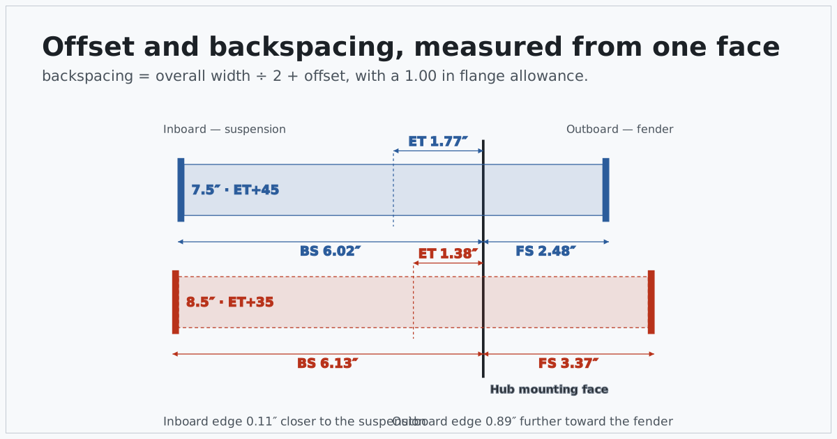
Take a change from a 7.5 inch wheel at ET+45 to an 8.5 inch wheel at ET+35. Both numbers move, in opposite senses: the wheel is wider, which pushes both edges outward from its own centre, and the offset is lower, which pushes the whole wheel outboard.
| Measurement | 7.5 in, ET+45 | 8.5 in, ET+35 | Change |
|---|---|---|---|
| Overall width | 8.50 in | 9.50 in | +1.00 in |
| Backspacing | 6.02 in | 6.13 in | +0.11 in |
| Frontspacing | 2.48 in | 3.37 in | +0.89 in |
| Inboard edge movement | reference | +2.7 mm | toward the suspension |
| Outboard edge movement | reference | +22.7 mm | toward the fender |
The inboard edge moves 2.7 mm toward the suspension and the outboard edge moves 22.7 mm toward the fender. Those two numbers are wildly different, and that asymmetry is the whole reason the two edges have to be reported separately. An extra inch of width split evenly would move each edge by 12.7 mm; the 10 mm drop in offset then adds 10 mm outboard and removes 10 mm inboard, which nearly cancels the inner movement and nearly doubles the outer one.
Read as a single number — "one inch wider, ten millimetres less offset" — that change sounds symmetrical. It is not, and the drawing at the top of this page is the clearest way to see it: the two wheels share a mounting face, and only the edges move.
Measuring backspacing on a wheel you already have
Backspacing is the one of the three you can measure yourself without specialist equipment, which is why it survives in the aftermarket despite offset being what the wheel is stamped with.
Lay the wheel face down, so the outboard face is on the floor and the mounting face points up. Lay a straight edge across the inboard rim edge, spanning the barrel. Then measure from the underside of that straight edge down to the mounting face. That distance is the backspacing. The straight edge has to rest on the rim edge rather than on a flange lip or a bead, and the ruler has to be square to it, because a few degrees of tilt reads as a few millimetres of extra depth.
Two things to watch. The mounting face is the machined pad the hub touches, not the top of a centre cap recess or the face of a spoke. And wheels with a lip or a stepped barrel can present more than one candidate edge at the inboard end; the one you want is the outermost inboard edge, which is the one that will meet the suspension first.
Measuring offset directly is harder, because the centreline is not a feature you can put a ruler against — it is halfway across the overall width, which means measuring the overall width first and then halving it. In practice it is easier to measure backspacing and convert, which is the direction the wheel offset calculator handles with either field as the input.
Poke, tuck and the thing offset really changes
Everyday language around offset is about appearance: a wheel that sits proud of the fender is described as poking, one that sits inside the arch as tucked. Both are descriptions of frontspacing relative to the bodywork, and the calculator reports that movement precisely.
What offset changes mechanically is less visible. Moving the wheel's centreline outboard moves the contact patch outboard relative to the steering axis, which lengthens the lever arm between them. The steering and the suspension were designed around a particular arm length, and changing it changes how braking and tractive forces feed back into the steering, and how much load the wheel bearing sees from a given cornering force. The bearing argument is simple leverage: the wheel's load is applied further from the bearing, so the moment on it goes up.
None of that is captured by a single clearance figure, and none of it is quantified by this site, because it depends on suspension geometry nobody can derive from a wheel specification. What the arithmetic here can tell you exactly is how far the centreline moved, which is the input to that discussion rather than the answer to it.
What the numbers cannot settle
Offset and backspacing describe where the rim sits across the hub face. They say nothing about several things that decide whether a wheel actually fits.
- Spoke and barrel shape. Brake caliper clearance depends on the inner profile of the spokes and barrel, not on a single plane. Two wheels with identical width and offset can differ on caliper clearance.
- Clearance at articulation. The gap you can measure with the car on the ground is not the gap at full suspension compression with the steering at full lock, and the two sides of an axle do not always measure the same.
- Scrub radius and steering. Moving the wheel's centreline outboard changes the geometry the steering works against. The effect is real, and nothing in this arithmetic quantifies it.
- Load rating and the bolt pattern. Both have to be right independently. The bolt circle is covered in the bolt pattern guide, and the axle load you must satisfy is on the vehicle's Tire and Loading Information label, where NHTSA directs you.
- The tire. A taller or wider tire changes the clearance picture on top of whatever the wheel does. Run the tire change through the tire size calculator before concluding anything about a combined change.
The short version
One mounting face, three distances. Offset runs from that face to the wheel's centreline, backspacing to the inboard edge, frontspacing to the outboard edge. Half the overall width connects them, so a width must accompany any offset or backspacing figure for either to mean anything, and a listing that quotes one without the other has not given you enough to work with. Overall width is the nominal bead-seat width plus a flange allowance, conventionally one inch, and that allowance is an assumption rather than a measurement.
Having wheel offset vs backspacing straight in your head is mostly about remembering which end each one is measured from, because once you know that, the conversion is half a width and the consequences are two edges moving independently.
Sources
- Modern Tire Dealer, Wheel Dimensions (published 2002-01-01) — definitions of zero, positive and negative offset, backspace, and rim width measured bead seat to bead seat. Retrieved 2026-10-16.
- NHTSA, Tire Safety Ratings and Awareness — the Tire and Loading Information label as the source for a vehicle's loading figures. Retrieved 2026-10-16.
- Every dimension in the tables above is computed from the formulas on the methodology page, with a 1.00 inch flange allowance unless stated.
Frequently asked questions
In wheel offset vs backspacing, which one should I use?
Use whichever the parts in front of you are labelled with, and convert when you need to compare. Offset is stamped on most modern wheels as ET followed by a number in millimetres, so it is usually the one you can read off the part. Backspacing is easier to measure yourself with a straight edge and a ruler. They describe the same geometry from opposite ends of the wheel.
How do I convert offset to backspacing?
Backspacing equals half the overall width plus the offset. Overall width is the nominal width plus a flange allowance, conventionally one inch total. For an 8.0 inch wheel at ET+35: overall is 9.0 inches, half is 4.5 inches, and 4.5 inches plus 35 mm (1.38 inches) gives 5.88 inches of backspacing.
Why does the conversion need the wheel width?
Because offset is measured from the wheel's centreline and backspacing from its inboard edge, and the distance between those two points is half the wheel's width. Without a width, +35 offset and 5.88 inches of backspacing cannot be connected. A bare offset figure says nothing about clearance on its own.
Does a lower offset always push the wheel out?
A lower offset moves the mounting face toward the inboard side of the wheel, so at the same width the whole wheel sits further outboard. But width changes both edges too. Going from 7.5 inches at ET45 to 8.5 inches at ET35 moves the outboard edge out by 22.7 mm and the inboard edge in by 2.7 mm, so the two effects do not cancel.
What is negative offset?
Negative offset means the hub mounting face sits inboard of the wheel's centreline, so more of the wheel is outside the mounting face than inside it. It is common on wheels designed for a wide track. Positive offset is the opposite and is what most front-wheel-drive and modern passenger cars use.
Will the calculator tell me if a wheel clears my brakes?
No. Offset and backspacing describe where the rim sits across the hub face; brake clearance also depends on the shape of the wheel's inner barrel and spokes, which no single number captures. Clearance is a measurement on your own vehicle, with the suspension compressed and the steering at full lock.